|
Henan Sanxiong Heavy Industries CO., LTD
|
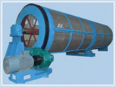
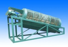
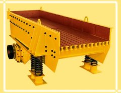
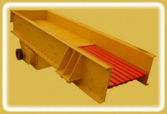
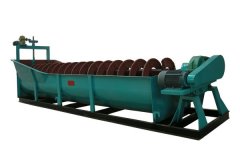
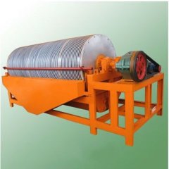
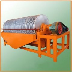
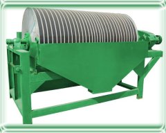
the Best Flotation Machine on sale
| Payment Terms: | T/T,L/C,D/P |
| Place of Origin: | Henan, China (Mainland) |
|
|
|
| Add to My Favorites | |
| HiSupplier Escrow |
Product Detail
1.large capacity of air suction
2.various design
3. hell install and debug production line
4. customized service
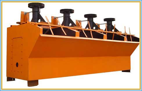
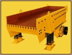
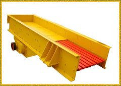
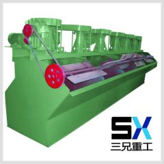
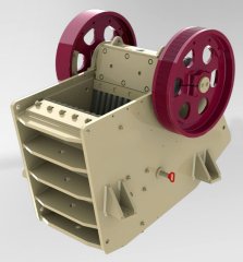
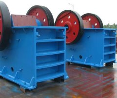
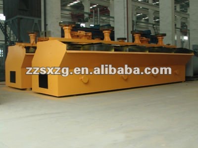
Red flotation machine in factory!
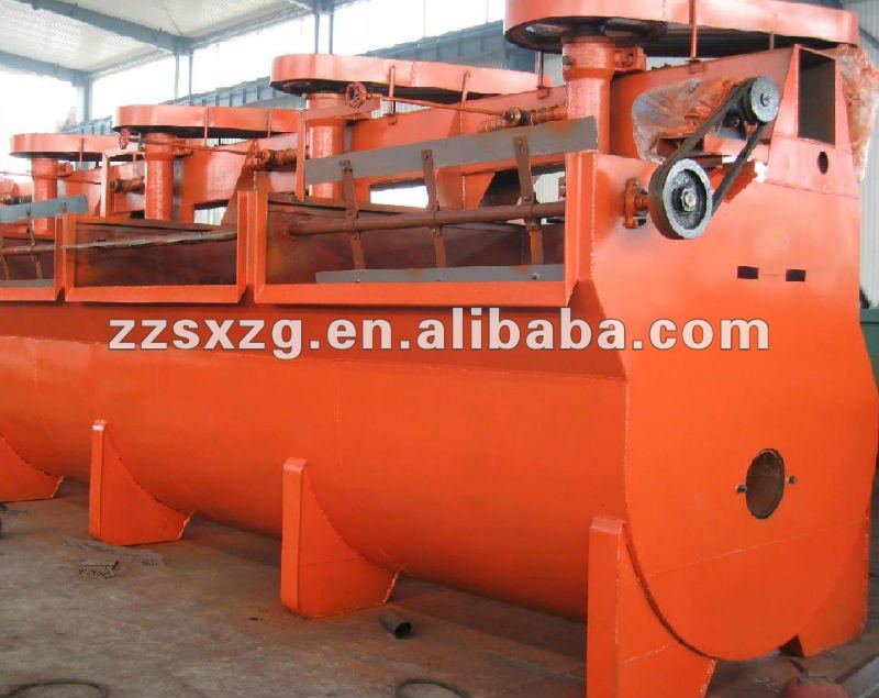

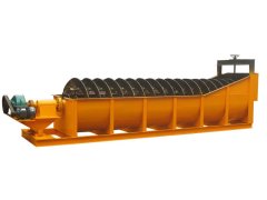
This type of flotation machineis formed by U through solid, hollow shaft inflation, suspension rotorand new type impeller. The cone impeller lean backwards, the blendingquantity is big and the pressure head is small, the advantages are:simple structure and low energy consumption. Inside the impeller, thereis air distributor, which distributes air into most parts of impellerevenly.
Flotation machine technical parameter:
Model | Trough cubage (m³) | Impeller | Power | Capacity (M³/min) | Overall dimension (m) | Weight (kg) | ||
Dia. (mm) | Speed (r/min) | Impeller (kw) | Scraper (kw) | |||||
SF0.15 | 0.15 | 200 | 536 | 1.5 | 0.55 | 0.06-0.18 | 0.5*0.5*0.6 | 538 |
SF0.37 | 0.37 | 296 | 386 | 1.5 | 0.55 | 0.2-0.4 | 0.7*.07*0.75 | 936 |
SF0.7 | 0.7 | 350 | 400 | 3 | 1.1 | 0.3-0.9 | 0.9*0.82*0.95 | 1200 |
SF1.2 | 1.2 | 150 | 312 | 5.5 | 1.1 | 0.6-1.2 | 1.1*1.1*1.1 | 2745 |
SF2.8 | 2.8 | 550 | 268 | 11 | 1.1 | 1.5-3.5 | 1.7*1.6*1.15 | 4676 |
SF4 | 4 | 650 | 220 | 15 | 1.5 | 2-4 | 1.85*2.05*1.2 | 5165 |
SF8 | 8 | 760 | 191 | 30 | 1.5 | 4-8 | 2.2*2.9*1.4 | 4129 |
SF10 | 10 | 760 | 191 | 30 | 1.5 | 5-10 | 2.2*2.9*1.7 | 4486 |
SF20 | 20 | 760 | 191 | 30*2 | 1.5 | 5-20 | 2.85*3.8*2 | 9823 |
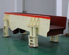
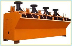
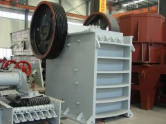
Flotation machine in workshop!
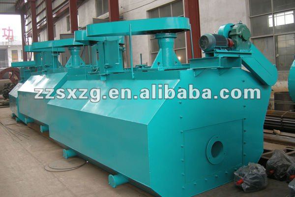

When flotation machineworks, slurry is inhaled from the bottom of the trough to the spacebetween impellers. Meanwhile, the low pressure air send by fan is sentto this area through the air distributor in the hollow shaft. Aftersufficient mixing, the slurry is pushed out by the impeller, and thengoes to the whole trough. When the froth rises to the stable level,after the enrichment processing, froth overflows to the froth troughfrom the overflow weir. Another part of ore slurry flows to lower partof impeller for the re-mix with air. The remained slurry flows to thenext trough until becomes residue.

Provide full machinery as well as mineral processing solutions!
Related Search
Flotation Machine
Packing Machine
Cutting Machine
Printing Machine
Sealing Machine
Filling Machine
More>>

